

please check the Part1 before continuing to this part2
1. Identification of loads:
a. Permanent loads:
The permanent loads applied to the structure are:
The weight of the structure, which is made of steel E42
b. Exploitation charges:
The operating expenses applied to the structure are: (See table 27)
The weight of the pipes
The weight of the fluid
The weight of the electrical tracing
The weight of the insulation
Overload: Add 20% of the loads for possible passage of pipes
In progress.
Maintenance Overhead: 100 DaN
Weight of the platform made up of: Quail about is - ladder - railing
Effort due to dilation: they are applied to the sleepers that contain the
Pipe supports such as guides, axial stop, and anchor took from the calculation note
Of the pipelines carried by the rack.
Element
|
Weight
|
Electrical Tracing
|
Pt=50Kg
|
lagging
|
Pc=21 Kg
|
Conduct
|
Pcdte= 193 Kg
|
Fluid
|
Pf= 137 Kg
|
Weight of the platform
|
Pplf= 100 Kg
|
Maintenance charge
|
Pmaint=100 Kg
|
Total weight
|
Ptot=674 Kg
|
Table: Total weight applied to the rack
The table below shows the expansion forces due to the supports:
Mounting Type
|
Fx (N)
|
Fy (N)
|
Axial stop
|
465
|
208
|
Guide
|
1211
|
48
|
Table 28: Expansion stresses due to rack-mounted media
c. Climatic loads -Wind:
In order to determine the effects of the wind on the rack, Annex 9 was used to determine
Of wind actions on the planar elements of the lattice constructions of Regulation NV 65 and
Each element has been isolated in order to define its geometric characteristics and
aerodynamic.
The formula used in Annex 9 is as follows:
𝐹 =. 𝑞. 𝑒. 𝑙
With:
F: The resultant of the forces applied by the wind
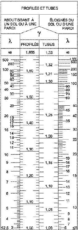
Ct: The drag coefficient - Paragraph R-III-3,2 of Regulation NV 65 defines the parameter
By the following formula: Ct = γCt0
In our case, the coefficient γ will allow correcting the value of C too when the ratio of
Dimension will not comply with the conditions: λ less than 2.5 in the case of
Vertical generators resting on the ground, and λ less than 5 for generator constructions
Vertical or horizontal generators. The values of γ are
Table 15 of Annex 9 to Regulation NV 65, as a function of λ.
Figure: Correction coefficient γ
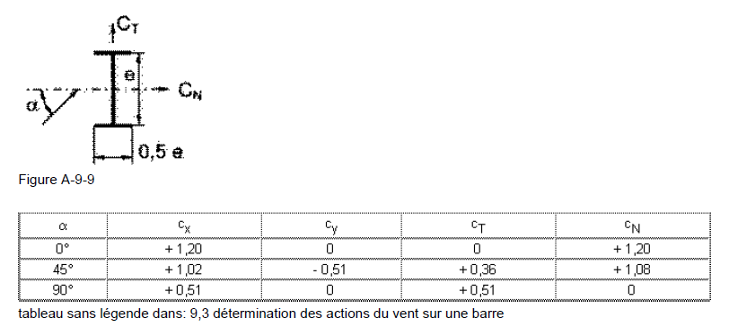
Table: Trajectory coefficient for IPE
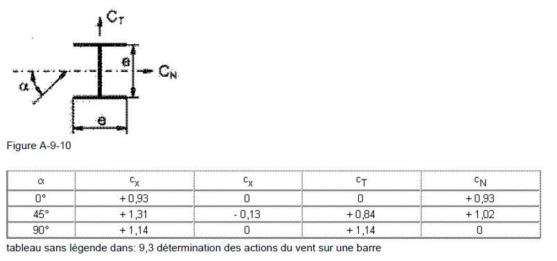
Table 30: Trainer coefficient for HEB:
Q: Dynamic wind pressure
E: The width of the face offered to the wind
L: The length of the face offered to the wind
The values of the wind loads in the two directions are shown in the table below
profile
|
l/e
|
Γ
|
Ct0
|
Ct
|
Q
(daN/m²)
|
W1
(daN)
|
W2
(daN)
|
IPE200 Secondary beam
|
1,5/200.10-3 =7,5
|
1,2
|
1,2
|
1,44
|
qx=106
|
45,79
| |
IPE220 Main beam
|
1,5/200.10-3 =7,5
|
1,2
|
1,2
|
1,44
|
qx=106
|
45,79
|


0 Comments